|
|
|
|
|
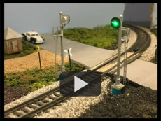
This video has good tips on signal installation,
video by Tony Bowen
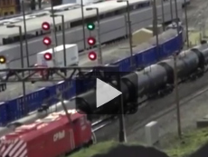
Video of the Dry Hill Model RR Club's layout at the 2019 Amherst Railroad Hobby Show.
video by Burack Cinematic
|
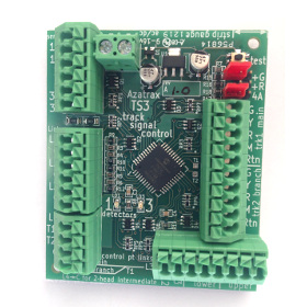
Block Signal Control for Model Railroads
Azatrax TSx series
Infrared (IR) train detection eliminates the need for insulated rail gaps and resistor wheel sets.
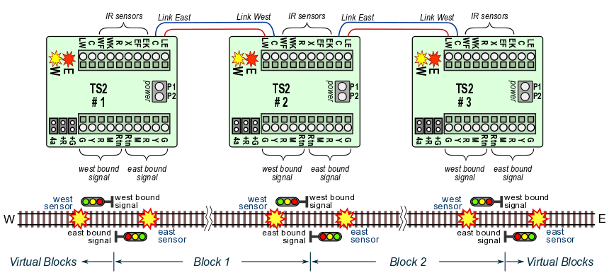
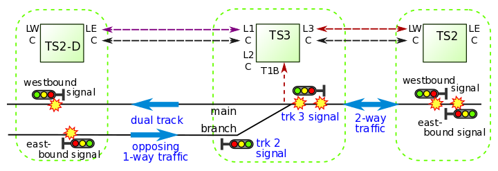
One TS2 circuit operates two LED train signals on a single bi-directional track:
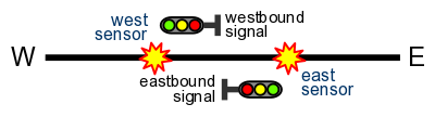
Two block signals at a block boundary, single 2-way track
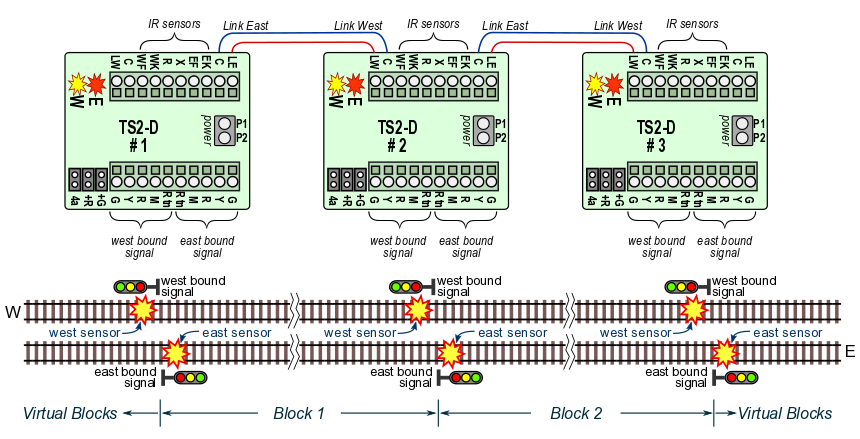
One TS2-D circuit operates two LED train signals on a double-track line:
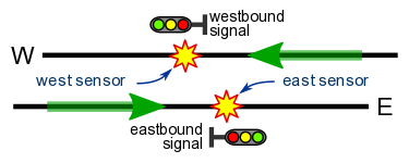
Two block signals at a block boundary, dual one-way tracks
One TS3 circuit operates three trackside signals at the junction of two tracks:
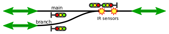
Three trackside signals at a track switch
For double track bi-directional signaling, see the
TS5 control point page.
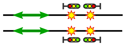
Four block signals at a block boundary, dual bi-directional tracks
|
Any number of TSx (TS2, TS2-D, TS3, TS5) circuits may be linked to operate a series of cascading block signals:
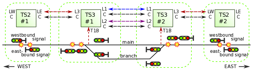
Above -- a passing siding with home and distant signals at both ends uses two TS2 and two TS3 circuits.
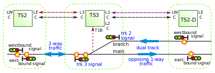
Merging a single 2-way track with two 1-way tracks.
Simple installation
- Don't worry about rail gaps or resistor wheel sets. The TSx circuits include very reliable infrared train detectors to sense train activity.
Compatible with "dead rail" (battery on board) operation.
- Don't worry about the polarity of your LED signals. The TSx circuits are "polarity smart" - they automatically adapt to common-anode (+) or common-cathode (-) signals.
- Don't worry about LED resistors. Current-limiting resistors are built into the TSx circuits.
- Don't worry about programming or addressing. The TSx are ready to wire up and go!
Click here for IR sensor installation tips.
|
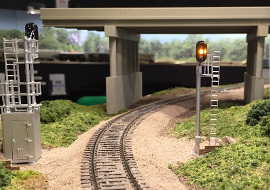
The installation of a TS2 signal system is documented on the Michigan Interstate St. Clair Sub blog site, including photos, video and a detailed narrative.
Greg McComas photo
|
Designed with modular layouts in mind
- Two adjoining layout modules that each have a TSx signal control circuit can be linked with just two wires per track. The signals on the two modules will then operate together.
- If the next module does not have a TSx circuit then your TSx will automatically sense this and will operate in a timed mode. Signal aspects will change after a train goes by according to a built-in timer.
|
- The pulsed infrared train detectors are not affected by changes in room lighting. Moving to a new location or turning down the lights for night operation? No re-adjustment needed!
- 3-aspect or 4-aspect operation (see below).
- Lamp on/off fading effect.
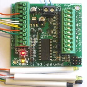
- Spring terminal blocks for quick wire connections.
- Power required: 9 to 16 volts AC or DC.
One PS1215 power supply will power up to twelve TSx circuits with signals.
- The TSx signal circuits are designed specifically to work with LED block signals of any scale.
For signals that have incandescent bulbs, solid state relays such as our SSR6 must be used between the TSx and the signal.
- Block signals sold separately:
|
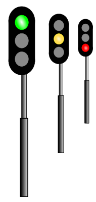
Supported
signal types
|

2 LEDs
|
 
3 LEDs
incl. searchlight signals
with single tri-color LED
|

B&O color position light
with marker
|

PRR
|

Searchlight with
bi-color LED (red/green)
2-wire or 3-wire
[see note below]
|
2 aspects
• clear
• stop
|
• green
• red
|
• green
• red
|
• green
• red
|
• vertical
• horizontal
|
• green
• red
|
3 aspects
• clear
• approach
• stop
|
n/a
|
• green
• yellow
• red
|
• green
• yellow
• red
(marker on or off)
|
• vertical
• diagonal
• horizontal
|
• green
• yellow
• red
|
4 aspects
• clear
• advance appr
• approach
• stop
|
n/a
|
• green
• flashing yellow
• yellow
• red
|
• green, marker on
• yellow, marker on
• yellow, marker off
• red, marker on
|
n/a
|
• green
• flashing yellow
• yellow
• red
|
Note: There are two kinds of LED searchlight signals sold for model railroads:
- Bi-color (red/green) - With two or three wires, this is the older type. The red and green portions of the LED are illuminated together to imitate a yellow color. The effectiveness is highly variable depending on the LED itself, ambient lighting and viewing angle. Looking from one side, the 'yellow' signal may appear almost red, and from the other side it may appear very green.
Though the TSx circuits have a jumper setting that allows you to adjust the yellow aspect with more red or more green to compensate, we recommend evaluating one signal first before purchasing signals in quantity.
- Tri-color (red/yellow/green) - Newer searchlight signals are available with tri-color LEDs that have a real yellow chip inside the LED, plus the red and green chips. You can easily spot these signals because they have four wires (red, yellow, green and 'common'). They show a real yellow color from all angles and under all lighting conditions. Use tri-color LED searchlight signals for best appearance.
TSx Limitations:
- The TSx detect trains only when they pass by the block boundary.
When linked to another TSx - After a train enters a block, the TSx assumes that block is occupied until a train exits that block. If part of the train uncouples and remains in the block while the rest of the train exits the block, the TSx can only sense that a train exited the block and will then show the block to be clear.
Therefor, where track is not visible to operators, supplemental detection may be used with the TSx circuits to detect stranded rail cars or other obstructions.
- While its power is turned off, the TSx cannot sense if trains are added or removed from the track. Therefor, when power is turned on, all signals will initially show an 'approach' aspect to let operators know they should proceed with caution. After the first train passes the infrared sensors, the signals will operate normally.
Interlocking controls:
Forcing a 'stop' condition:
- A signal may need to show a 'stop' indication for an open turnout or draw bridge in the block, for an indication from another train detector, or by command of a dispatcher. Use a switch or relay contact to connect a 1,000 ohm (1k) resistor between the Link ('LE' or 'LW') and 'C' of the TSx to force a 'stop' indication. This works in linked or stand-alone mode.
Clearing a block:
- An 'occupied' ('stop') signal indication may be manually cleared by momentarily shorting Link ('LE' or 'LW') to 'C' with a push button. You may want to do this if a train exited a block by some route other than passing a TS2 / TS2-D at the block boundary - perhaps it took a branch line or was removed by hand.
|
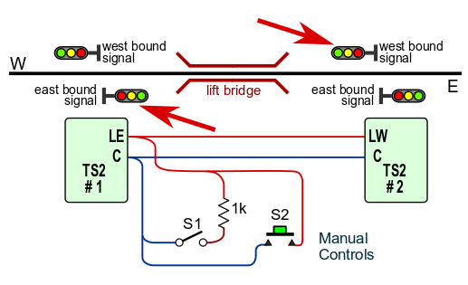
Closing switch S1 will force #1 eastbound signal and #2 westbound signal to show 'stop.' S1 may be linked to a drawbridge, turnout points, a train detector or a dispatcher's switch.
Momentarily closing switch S2 will clear the block between TS2 #1 and TS2 #2.
|
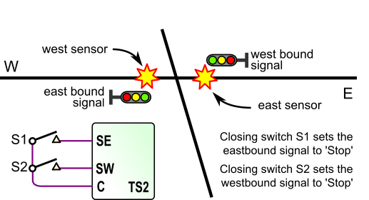
To create a 'stop' condition at one location,
rather than for an entire block as shown above, use a switch or relay to connect terminals 'SE' and 'SW' to a 'C' terminal.
In this example, the east/west main line is crossed by a north/south track. Closing switch S1 sets the eastbound signal to 'stop' and closing switch S2 sets the westbound signal to 'stop.' This allows a train to safely cross on the north/south track.
The two IR sensors may be placed on opposite sides of the crossing as shown here, or they may both be on the same side.
|
|
Use with block occupancy detection:
Current sensing block occupancy detectors can be used with the TS2, TS3 and TS5 signal controllers,
either to supplement the IR sensors at certain locations, or to replace the IR sensors.
Each block occupancy detector must have an isolated output, either a relay contact or an opto-isolator.
Click here for more details [pdf].
© copyright 2009-2023 Azatrax LLC, Longmont, Colorado
|
|