|
|
|
|
|
Model Railway Reverse Loops
How to automate reversing tracks on your two-rail layout, whether DC, DCC or AC powered
|
Because of the way power is supplied to electric model trains, two-rail layouts require special treatment of reversing tracks. Wiring reversing tracks (reverse loops or wyes) is a mystery to some modelers, so they avoid using them on their layouts and miss out on the benefits of having a reverse loop or wye track.
If reverse loops and wyes are controlled by manual switches, the train operator must flip them in proper sequence. A moment of inattention results in a short circuit or derailment. This is especially likely (and embarrassing) when operating the layout for visitors.
On this page we briefly explain the theory of two-rail reverse loop operation, then show you how to completely automate them. Enjoy the benefits of reverse loops without the operational headaches.
Are you looking instead for an automatic back-and-forth control?
[ click here for the point-to-point train shuttle controller ]
The Why and How of reverse loop wiring
[ or click here to skip the theory and go straight to the solution ]
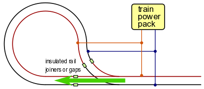 The first diagram shows a train (green arrow) entering a two-rail reverse loop. The insulated rail joints are necessary because without them, electricity would flow from one side of the power pack, around the loop and directly back to the other side of the power pack. This would be a short circuit and would prevent the train from getting power. It would also pop the circuit breaker in the power pack.
The reason for two sets of insulated rail joints and the two sets of electrical connections to the power pack will be shown in the next two figures.
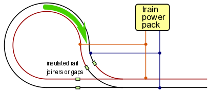 The train travels around the loop and is approaching the exit, ready to rejoin the main line.
But there will be a problem when the train attempts to cross the insulated rail joints where the loop meets the main line.
The metal wheels of the locomotive will bridge the insulated joints, creating short circuits. Electricity from one side of the power pack will be able to return directly to the other side of the power pack. The train will not receive power, and the circuit breaker in the power pack will trip.
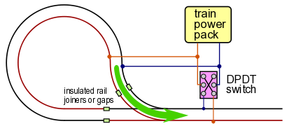 The solution is to swap the power pack connections at the main track before the train leaves the loop. This is done with a DPDT (double pole, double throw) toggle switch or relay as shown in the third figure.
For layouts that are powered by DCC or AC power supplies, we have the option of swapping the power connections to the loop instead of the main line. All that matters is that the power connections match at the insulated joints where the train is ready to cross.
On layouts with DC power, the track power connections must be swapped on the track that is not occupied by the train. On DC layouts, the track polarity (which rail is positive vs. negative) determines the direction of train travel. If we changed the polarity of the loop power while the train is in the loop, the train would suddenly change direction. Therefor we must change the main track polarity while the train is on the loop track.
As you can see, every time a train travels around the reversing loop, the track polarity must be changed and the track switch must be set. If left to manual control, these are two opportunities for error. [ Click here to go to the automatic reversing loop controls page ]
© copyright 2009-2023 Azatrax LLC, Longmont, Colorado
|
|