|
|
|
|
|
Azatrax D2T dual infrared model railroad detectors
For automated track turnout control, signal control and direction sensing.
|
The D2T combines two infrared train detectors into one circuit module. Each detector consists of an infrared LED light source and a phototransistor light receiver.
Each IR LED / receiver pair may be placed in the track roadbed for reflective sensing, or mounted above and beside the track for across-the-track sensing. See the D2T installation guides for details about reflective and across-the-track train sensing.
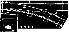
Automatic Turnout Control / 'Non-derailing' Switch Control
The switch points are automatically aligned for an approaching train to avoid derailments.
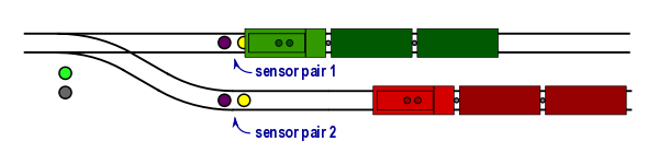
In this example, two trains are approaching a track switch from the right. The green train arrives at sensor pair 1, and the D2T aligns the switch points to the straight track.
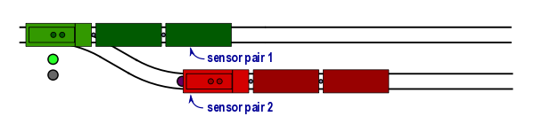
Now the red train arrives at sensor pair 2. The D2T will not throw the turnout points because sensor pair 1 is still sensing the green train.
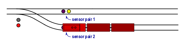
Four seconds after the green train has cleared sensor pair 1, the D2T will respond to sensor pair 2 by aligning the turnout points with the siding.
Additional protection against throwing the points while a train is on the points can be provided with an external train detector such as our MRD1 single detector (sold separately). Place the external detector's sensors at the switch points, and connect the detector's output to the D2T.
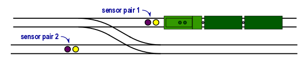
Avoid derailments at a single cross-over
You can configure a D2T to protect the two turnouts at a single cross-over. Place one IR sensor on each of the parallel tracks, ahead of the switch frog. If a train is detected at either IR sensor, both turnouts will be set to the 'straight' position.
A manual push button is required to set the turnouts to the cross-over position.
Manual Turnout Control
The switch points can be controlled manually by connecting push buttons to the D2T circuit board. Push buttons are not included with the D2T.
Auxiliary Relay Contacts
The D2T includes single pole relay contacts that switch according to the position of the turnout points. These contacts are rated for up to 3 amps and may be used to control signal lights or to route track power to sidings or to the switch frog.
Spring Switch Simulator - "SS" versions
 Enhance your operations with a spring switch simulator.
A spring switch, also called a "run-through" switch, allows a train to enter the main line from a branch track without human intervention. In remote areas it saves the train crew from having to stop and reset the switch after entering the main line and walking back to the locomotive. It eliminates the risk of someone forgetting to reset the switch.
Using a spring switch version of the D2T-2W or -3W on a reversing loop
will ensure that every train that enters the loop will travel around the loop in the same direction
(DCC or AC track power, not for DC reverse loops).
|
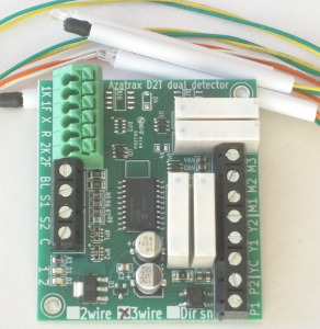
D2T kit includes circuit board, two infrared (IR) LEDs, two IR receivers and hardware
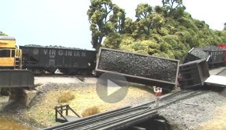
Model Railroader magazine has produced an entertaining video highlighting the main features of the D2T-2W and -3W turnout controller.
Check it out!
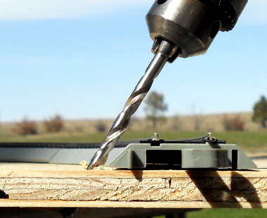 Click the drill to learn how to install the IR sensors.
|
Choose from the following D2T models:
D2T-2W turnout control for 2-wire switch machines
Two-wire switch machines include single-coil 'snap' switches such as Kato™, LGB™ and Aristocraft™
as well as slow motion switch machines such as
Tortoise™, Cobalt Classic™ and SwitchMaster™
|
|
|
|
D2T-3W turnout control for 3-wire switch machines
Three-wire switch machines, also known as twin-coil or dual-solenoid switch machines, include Atlas™, Bachmann™, Kemtron™, Peco™ and American Flyer™.
|
|
|
|
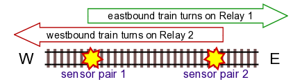
D2T-DS direction sensing train detector
Activates two different circuits depending on train direction. Sometimes you only want to activate a circuit or accessory if the train is moving in one direction, but not when it is moving in the other direction.
You can set up a D2T-DS for one of the following modes:
- Normally open, momentary - for actuating 'snap' switch machines or solenoid-operated semaphores that require brief momentary power only.
- Normally open, sustained - turns on a signal or other circuit when the train is between the two IR sensors.
- Normally closed, sustained - turns off a circuit when the train is between the two sensors.
|
|
© copyright 2009-2023 Azatrax LLC, Longmont, Colorado
|
|