|
|
|
|
|
How to install Azatrax IR proximity sensors for model trains
|
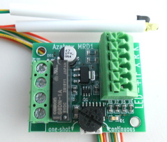
The Azatrax IR(infrared) train detectors are designed to be easy and simple to use, yet versatile and flexible. Each detector consists of a circuit board and one or more sensor sets: an IR LED light source paired with an IR receiver. The infrared light is not visible to the human eye.
The IR LED and receiver are pre-assembled with wire leads and are supplied with plastic tubes 3/16 inch (4.8mm) outside diameter to facilitate installation.
The train detector circuits may be set up with the sensing elements mounted above the layout surface so that they look across the track, or for reflective sensing, with the sensing elements typically embedded in or next to the track roadbed.
• Reflective sensing can see a train at only one spot.
• Across-track sensing can cover a longer stretch of track when the IR LED and its receiver are placed at an angle across the track. The shallower the angle, the longer the length of covered track. The IR LED can be as far as 18 inches (45cm) from its receiver when used in across-track configuration.
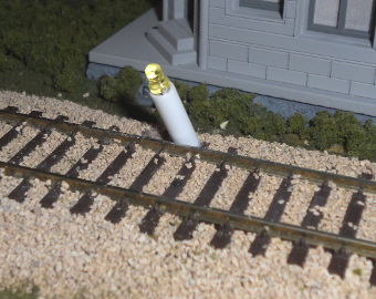
Reflective sensing (sensors in the roadbed)
The detector is active when the receiver sees the infrared signal sent by
the IR LED.
|
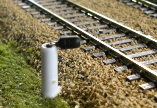
Vertical sensor installation works well for S scale and larger.
|
Installing sensors at an angle improves sensing at close range, such as with HO scale and smaller.
This also reduces false sensing from overhead objects.
|
Angled sensors between the rails. The sensors are pushed up to show where their centerlines meet. HO scale.
|
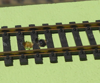
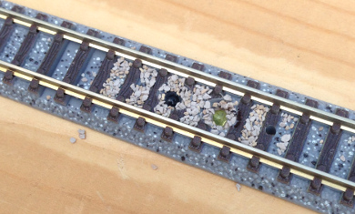
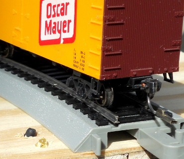
Reflective sensing, sensors between the rails. HO scale.
|
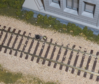
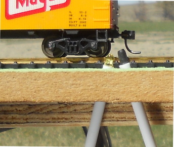
Placing sensors outside the rails at the sleeper ends helps make them less visually intrusive, especially if on the opposite side of the track from viewers. HO scale.
|
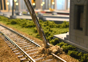
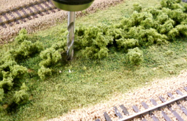
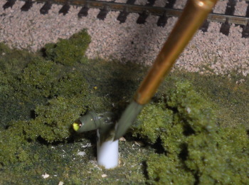
Drilling for sensors at the tie ends. Angle slightly toward the trains. Use a 3/16" (4,8mm) or the next larger size.
|
IR receiver, HO scale.
|
IR LED, HO scale.
|
IR LED and receiver, pushed up to show the angles. HO scale.
|
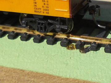
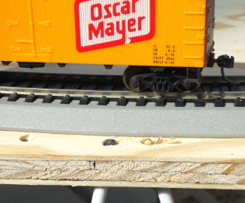
IR sensors beside the rails, HO scale.
|
Ballasting the track after sensor installation will not harm the IR sensors. Let the glue dry, then scrape the dried glue and ballast off the lens of the IR LED and receiver.
|
View from below the layout. Two tracks, N scale.
|
Reflective sensing on track with integrated roadbed
|
Drilling through N scale roadbed.
|
View from underneath, N scale.
|
Sensors in N scale track.
|
Back filled with ballast, N scale.
White glue or matte medium will not affect the sensors.
|
|
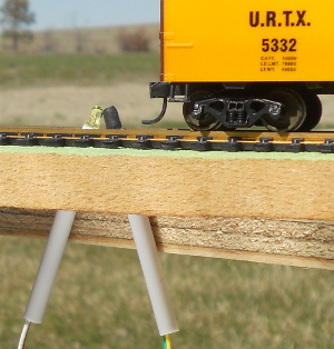
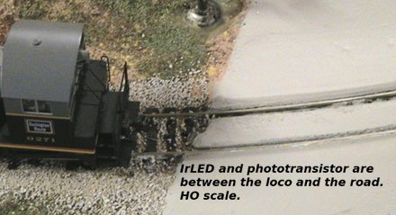
You can also use reflective sensing without drilling holes in your track's
built-in roadbed.
|
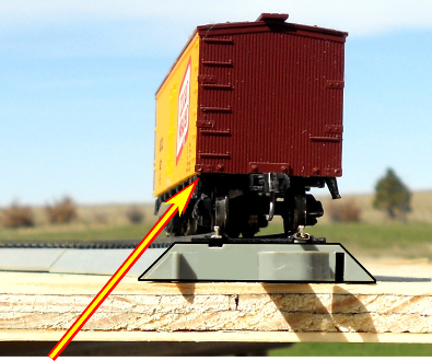
The sensors will be placed next to the roadbed, pointed at the lower edge of the rolling stock. The arrow shows the desired angle.
|
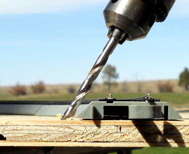
Drilling for sensor installation with pre-made roadbed,
like EZ-track™.
Use a 3/16" (4,8mm) or the next larger size.
|
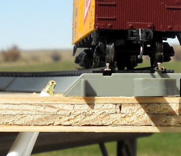
These sensors are pointing somewhat more vertically than intended. But they still work.
|
IR sensors next to HO EZ-track™ and pushed into place.
|
Side view with the IR LED and receiver extended to show how both are pointed at the same spot on the rolling stock.
|
Use white glue or similar to hold the IR LED and receiver in place.
|
Installation tip:
- File off any burrs on the insertion end of the plastic tube. Burrs or ridges can be left from the cutting process.
- Smoothing or slightly tapering the end will make it easier to insert the plastic tube, especially if going through layers of different materials.
|
|
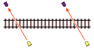
Interrupt sensing (sensors look across the track)
The detector is active when the receiver does not see the infrared signal sent by
the IR LED.
|
When the sensors are wired for across-track sensing, the detector activates when the light path is blocked.
|
Drilling for sensor installation. Use a 3/16" (4,8mm) or the next larger size. The IR LED and its receiver can be up to 18" (45cm) apart from each other, so they do not need to be placed right next to the track.
|
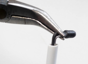
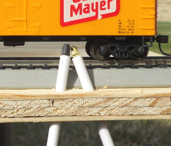
Across-track sensing is often done with the tubes placed vertically and the IR sensors looking horizontally.
Pull the sensor away from the tube. Support the leads with pliers and push the sensor over to a right angle.
|
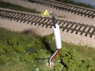
Installing IR LED from the top. This tube has been shortened due to limited space under the layout base.
|
IR receiver on the opposite side of the tracks from the IR LED.
|
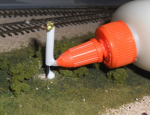
A drop of water soluble glue will hold the sensor in place.
|
IR LED and its receiver aligned facing each other.
|
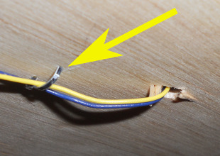
After aligning, fold the wires against the underside of the layout base. Clamp the wire to prevent the IR sensor from rotating.
|
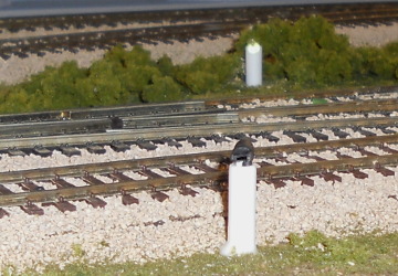
Paint the IR sensors and posts to blend with their surroundings. Keep the lenses clear.
|
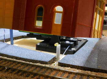
This building hides an IR sensor and a remotely mounted switch machine.
|
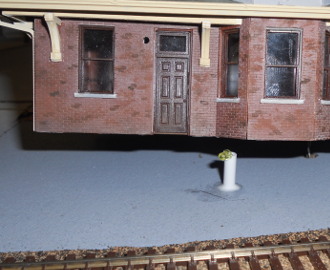
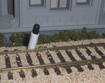
This IR LED will be covered by the station.
|
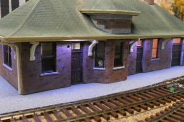
Clear or lightly frosted window glazing will not degrade the IR sensor performance.
|
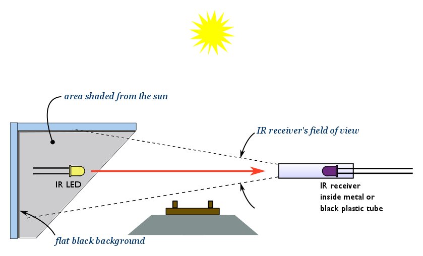
It is possible for the IR receiver to be saturated by bright ambient infrared light, such as from a sunny window or high wattage incandescent lamp.
If this happens, the detector will indicate that the infrared light beam is blocked even when the path is clear. To remedy this situation:
- Shield the IR receiver with scenery or a structure
- Swap positions of the IR LED and IR receiver so the receiver is not pointed at the offending light source
- If the light source is an incandescent bulb, change it to fluorescent or to an LED light. These produce far less infrared energy.
 Double coverage with two sensors:
When used in across-track sensing, one Azatrax train detector circuit can be wired to two sensor pairs. The detector will turn 'on' when a train blocks either of the two infrared light beams. See the double sensing page for details.
General wiring advice:
- Where two or more wires are connected to the same circuit board terminal, twist the bare ends of the wires together before inserting them
in the terminal block. Loose connections can be frustrating to track down.
- Route detector wires away from DCC power and control bus wiring. If detector wiring must cross DCC wiring, have the cables cross at right angles as much as practical.
-
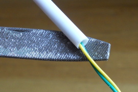
Additional wire may be spliced to the IR LED and receiver leads, up to 26 feet (8m). Use #24 or #22 gauge wire
(0,20 to 0,25 mm2).
The twisted pairs from telephone cable or 'Cat 5' network cables are excellent for this use.
- Use a power supply of 9 to 16 volts AC or DC.
Outdoor installations:
The infrared detectors can be used outdoors if you
- Keep the circuits and connections dry, and
- Shield the IR sensors from direct sunlight, see suggestions below.
Simple trackside signals.
You can have basic functioning red/green trackside signals using the MRD1 model train detector. Get started here...
Three-color red/yellow/green trackside signals can be operated with the TS2 and TS2-D block signal circuits.
Send comments or questions to us via our contact page.
© copyright 2009-2023 Azatrax LLC, Longmont, Colorado
|
|