|
|
|
|
|
How to wire the MRD1 and MRD8 Infrared Train Detectors to
two-aspect model railroad signals.
|
|
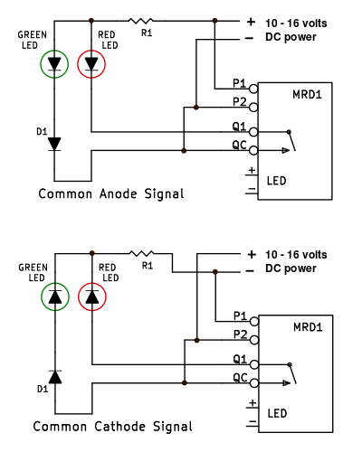
Here's how to use an MRD1 infrared train detector to operate a basic
red/green trackside signal or control panel indicators.
When the MRD1 detector senses a train, it closes its switch contact between terminals Q1 and QC, and the red LED
will light. When no train is sensed, the switch contact opens and the green LED will light.
Also required:
- R1 - 1/4 watt resistor, 800 to 2000 ohms
In most cases diode D1 is not needed. Connect the green LED directly to terminal QC or to the power supply.
If the green LED glows at the same time that the red LED is lit, then insert diode D1 in series with the green LED.
- D1 - diode, 1N4001, 1N4936 or similar
The IR sensor installation page shows how to install the infrared train sensors.
How it works: When the switch on the MRD1 is open, the red LED is removed from the circuit and the current from the
power supply flows through the green LED.
When the MRD1 senses a train and its switch closes, current flows through the red LED. But why doesn't the green LED
also light? Diodes have a "forward bias voltage" that must be overcome before they will conduct
current. A red LED typically has a forward bias voltage of 1.7 volts, a green LED forward bias voltage is
2.2 volts.
When the switch is closed, the voltage seen across the green LED is the same as the forward bias voltage of
the red LED, or 1.7 volts.
This is less than the forward bias voltage of the green LED, so only a very small leakage current will
flow through the green LED.
Note that each signal has one resistor in the common lead. Some signal manufacturers include
resistors in the individual lamp leads. To use the circuits on this page, each signal should only have a resistor
in the common lead. Any resistors in the individual lamp leads should be removed.
|
The LEDs in most commercially made model railroad signals are wired as
"Common Anode (+)."
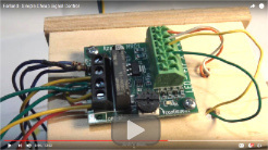
In this video Rob McCrain shows how to connect an MRD1-V to simple
2-light
European style signals.
With Rob's LEDs he did not need to use diode D1.
|
Control multiple two-aspect model railroad signals with the MRD8 Octal IR Train Detector
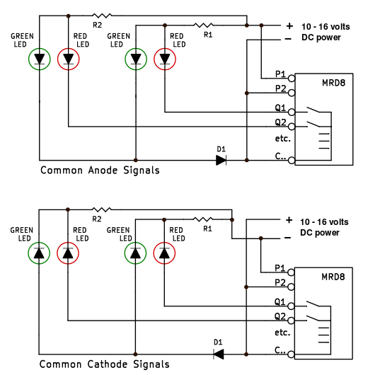 An MRD8 infrared train detector can control up to eight red/green trackside signals or panel board indicators.
As in the example above, when the MRD8 detector senses a train, it closes its relay contact between terminals Q1 (or Q2, Q3, etc.) and C14 (or C58), and the red LED will illuminate. When no train is sensed, the relay opens and the green LED will illuminate.
As above, the D1 diode is usually not needed. Connect the green LEDs directly to terminal C14 or C58 or to the power supply.
If the green LED glows at the same time that the red LED is lit, then insert diode D1 as shown in series with the green LED.
- D1 - diode, 1N4001, 1N4936 or similar
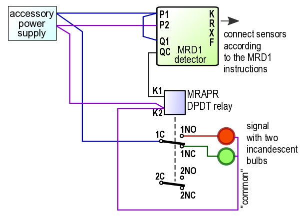 Signals with incandescent light bulbs:
To operate a two-lamp signal with incandescent lamps, an MRD1 or MRD8 detector requires a relay in addition to the detector circuit. See the diagram at the right.
When a train is detected, the detector circuit energizes the relay coil. The relay contacts 'pick up' and send power to the red bulb. When the train leaves the detector, the detector turns off the relay. The relay contacts drop down, disconnecting the red bulb and sending power to the green bulb.
Be sure the relay and the signal lamps can operate from the same power supply. Azatrax MRAPR relays will work on
AC or DC power.
You may send us questions or comments via the contact page.
© copyright 2009-2025 Azatrax LLC, Longmont, Colorado
|
|