|
|
|
|
|
Operating model railroad crossing gates
How to install working crossing gates on a model railroad layout.
|
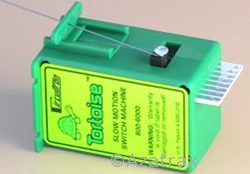
Create realistic crossing gate operation using Tortoise™ slow motion switch machines or R/C servos.
The Signal
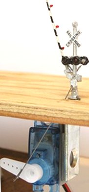
This example shows how to make operating crossing gates with O scale signals
by NJ International driven by Tortoise™ switch machine motors.
The motors move the gate arms at realistic speed when operated with an Azatrax MRX3 crossing signal controller.
HO scale and N scale installations are shown below.
The NJI gates come with an actuating wire that extends out the bottom of the base. Unfortunately, this wire is attached right at the gate's pivot point, so it requires a lot of force to move and has very short range of motion.
This wire is soft, so it can be removed with a firm, steady pull with pliers.
Drill a small hole in the crossing arm counterweight as far from the arm's pivot as practical. The goal is to create as much leverage as possible so the motors can provide smooth motion. The hole should be just large enough for your actuator wire. Piano wire, 0.015 or 0.025 in. dia. works well.
Mount the signal by shoving a length of 3/8 in. brass tubing firmly into the base. Run the wires through the tube. Drill a 3/8 in. hole in the layout, then place the signal.
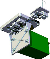
The Mechanism
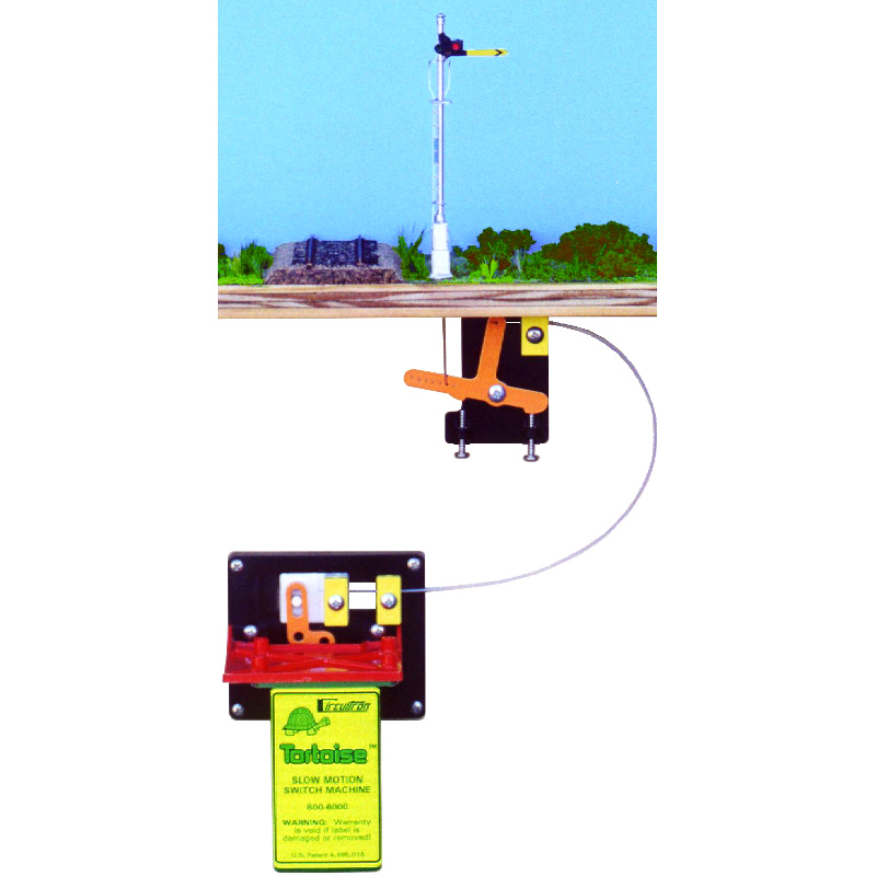
To provide vertical drive motion, the Tortoise™ switch machine must be mounted horizontally under the layout. Figure 2 shows how to do this.
Fig.2 shows the use of an 'L' bracket to mount the Tortoise switch machine motor.
A transverse wire connects the actuating wire to the motor output. The transverse wire allows the mechanism to have more 'give.' The movable fulcrum allows you to adjust the range of motion and change the mechanical advantage.
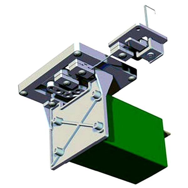
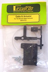
Alternatively, Circuitron's Remote Signal Activator kit may be used to mount the Tortoise™ switch machine motor and connect it to a crossing arm.
Your careful efforts installing working crossing gates will reward you and your visitors many times over.
|
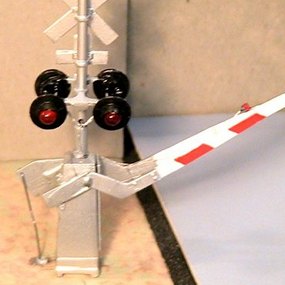
Fig.1 - Actuator wire connects to a hole drilled in the crossing arm counterweight.
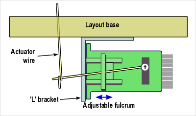
Fig.2 - Mounting the motor under the layout.
|
HO scale working crossing gates
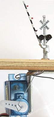
Josta refined the Tortoise™ mounting method and took these photos on his HO scale layout. He is using NJ International signals with crossing gates.
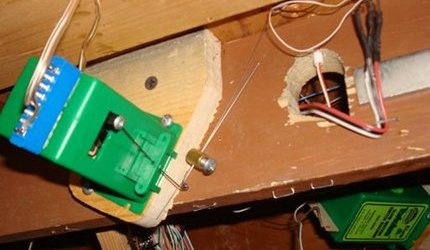 Josta ran the gate arm actuating wire at a 60 degree angle. He then mounted the Tortoise switch machines under the layout base at a 60-degree angle as well. He says,
"I used 0.030-inch music wire for the horizontal lever of the motor, and another 0.030 section of music wire for part of the vertical pushrod. These two wires are connected with tight loops at each end as the photo shows. Then I used a cable clamp (available at auto parts stores) to clamp the 0.015 music wire from the NJ gates to the 0.030 wire from the motor. Just loosen the clamp to move the gates to the desired up and down points.
"I move the fulcrum on the Tortoise motor as needed to give the desired range of motion. If there's too much play due to the flexing of the 0.015 wire, just move the cable clamp up closer to the gate; that's why I use 0.030 wire as it's stiffer."
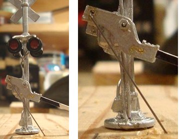 The actuating wire is 0.015-inch music wire, placed on the back side of the signal where it is not so easily seen.
See the smooth action of Josta's excellent installation in his YouTube video:
[http://www.youtube.com/watch?v=LeST0GnjOeg]
N scale crossing gate installation with Tortoise™ motor
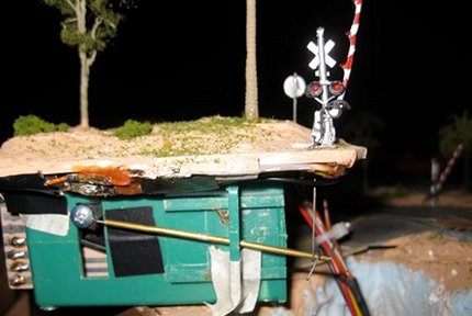
David Bilek placed this N scale NJI crossing gate and its Tortoise™ motor on a lift-out base to simplify assembly and maintenance. He can also take it with him when his layout moves.
David added LEDs to those N scale crossing gate arms and wired them to an Azatrax crossing signal controller so they flash in prototypical style. Amazing work, David!
N scale crossing gate installation with 9g R/C servo
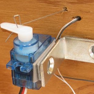
Model railroad crossing gates can also be operated with servo motors. Servos are widely used in radio controlled, or 'R/C' airplanes, boats and cars.
The three photos above show an N scale NJI crossing gate with a 9g mini-servo. Examples of this type of servo are HiTec model HS-55 and Futaba S3111.
Before mounting your servo, determine in which direction it will rotate! Not all servos are the same.
We have mounted the servo to the underside of a lift-out section with double-sided foam tape and a metal corner bracket, available in hardware stores. For best adhesion, remove any labels from the servo and clean the mounting surface with alcohol to remove oil and grease.
It is a good idea to build your crossing on a removable platform, particularly if you model in the smaller scales. The platform can be built and adjusted on a workbench, rather than making fine adjustments from underneath the layout.
A length of 0.015-inch (0.4mm) steel music wire replaces the actuating wire that came with the signal. Note the hairpin bend in the wire. Making this bend allows you to make small adjustments to the gate position.
The Azatrax MRX3 crossing signal controller will operate crossing gates with either Tortoise™ motors or servos.
Tortoise™ Remote Signal Activator (RSA)
Slow vertical motion for animated accessories
• Circuitron part no. 800-8100
• Remote mounting bracket & mechanism for Tortoise™ motor
• Cable actuation for one crossing gate, semaphore or other accessory with vertical motion.
• Easy precise adjustment of stops
• Download RSA installation instructions here [pdf]
• Tortoise™ motor not included (see above)
To operate a pair of crossing gates, use
one 800-8100 kit and one 800-8101 kit
with one Tortoise motor.
|
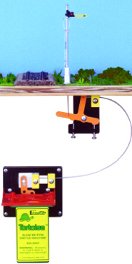
Tortoise™ Remote Signal Activator (vertical motion)
|
|
Tortoise™ 2nd Cable & Actuator
• Circuitron part no. 800-8101
• Use with Remote Signal Activator kit above to operate a second crossing arm with one Tortoise™ motor
• Easy precise adjustment of stops
|
Tortoise™ Add-on Cable & Actuator
|
|
Remote Tortoise™ Mount
Slow horizontal motion for turnout points where there is no room to place the Tortoise™ motor directly below the switch points.
• Circuitron part no. 800-6100
• Remote mounting bracket & mechanism for Tortoise™ switch machine.
• Cable actuator for one turnout or other accessory with horizontal motion.
• Download remote Tortoise™ installation instructions here [pdf]
• Tortoise™ switch machine not included (see above)
|
Tortoise™ remote turnout control (horizontal motion)
|
|
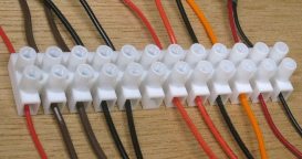
Tortoise™ wiring aid
• 12-circuit Euro-style terminal blocks
• Simplifies wiring Tortoise switch machines, signals and layout accessories
• White nylon housing, easy to cut to custom length
• Accepts wire sizes up to AWG 12
• Rated for up to 20 amps per circuit
 Tortoise™ switch machines are known for smooth operation and reliability. The one complaint we've heard is that it's difficult to connect wires to the Tortoise. It is awkward to solder wires while crouched under your layout. Tortoise™ switch machines are known for smooth operation and reliability. The one complaint we've heard is that it's difficult to connect wires to the Tortoise. It is awkward to solder wires while crouched under your layout.
Some layout builders have used circuit board edge connectors with varying degrees of success. The trouble with edge connectors is that you still have to solder wires to the connector, and this has to be done under the layout.
Our preferred way to wire a Tortoise™ motor is to:
• On the workbench, solder short wires to the Tortoise
• Place a terminal block under the layout near the planned motor location
• Mount the Tortoise according to instructions.
• Connect to the layout wiring via the terminal block
You still have to solder wires to the switch machine, but it is done safely at your workbench. All under-layout wiring is done with a screwdriver.
|
|
Tortoise™ edge connector and terminal block
|
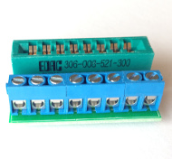
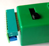
Accu Lites SNAPS! Wiring Connector
• Connector with screw terminal block fits tight to the Tortoise switch machine
• Eight position screw terminal block eliminates soldering
• Insert wires into the terminal block, then plug the connector onto the Tortoise after the Tortoise has been mounted under the layout
• Accu Lites part number 107-1001 (single) and 107-1006 (six-pack)
These connectors fit the pre-2020 Tortoise motors that have a tan-colored circuit card.
Newer Tortoise motors have a green-colored circuit card and will not fit these AccuLite edge connectors.
See the Circuitron website for more information.
|
AccuLites 1001 terminal
Tortoise motor sold separately
|
|
Tortoise™ and the turtle logo are trademarks of Circuitron, Inc., Romeoville, IL
© copyright 2009-2020 Azatrax LLC, Longmont, Colorado
|
|