|
|
|
|
|
How to wire Azatrax model train detectors as inputs to Digitrax™ DS64, DS74, SE8C and SE74 signal decoders.
|
SE8C:
Azatrax infrared train detectors can easily be wired as inputs to a Digitrax™ DS64 and SE8C Signal Decoders. This allows the SE8C to respond when a train arrives at a particular location on the layout.
MRD1, D2T and MRD8 train detectors are wired to the SE8C decoder in the same way as momentary push button switches or track block detectors. See the pin-out diagram for the SE8C edge connector in the Digitrax™ instruction manual.
Figure 1 on the right shows three Azatax MRD1 infrared train detectors connected to inputs SW01, DS02 and DS03 on a Digitrax™ SE8C. The SE8C has eight input connections for switch contacts, SW01 - SW08, and eight connections for track block detectors, DS01 - DS08.
- Connect SE8C pin 2 (+VE sensor common) to the QC terminal of each MRD1 detector.
- Connect the Q1 terminal of the first MRD1 to a DS or SW input on the SE8C. In this example the first MRD1 detector is connected to pin 4 (SW01).
- Connect the Q1 terminal of the each remaining MRD1 to other DS or SW inputs on the SE8C. If you want multiple MRD1's to trigger the same response from the SE8C, then connect a single DS or SW input to the Q1 terminals of all those MRD1 detectors.
- Connect an accessory power supply to all MRD1 detectors, terminals P1 and P2. The power supply should be 9 to 15 volts AC or DC.
Figure 2 on the right shows one Azatax MRD8 octal infrared train detector connected to inputs SW01 - SW04 and DS01 - DS04 on a Digitrax™ SE8C. You may connect the MRD8 outputs to any combination of DS and SW inputs on the SE8C.
- Connect SE8C pin 2 (+VE sensor common) to the C14 or C58 terminal of the MRD8 detector.
- Leave the jumper block on both pins of JMP1 on the MRD8.
- Connect the Q1 - Q8 output terminals of the MRD8 to the DS and SW inputs on the SE8C.
- Connect an accessory power supply to MRD8 terminals P1 and P2. The power supply should be 9 to 15 volts AC or DC.
DS64:
Figure 3 shows one Azatax MRD8 octal infrared train detector connected to the eight inputs of a Digitrax™ DS64 stationary decoder.
- Connect the DS64 +COM terminal to the C14 or C58 terminal of the MRD8 detector.
- Leave the jumper block on both pins of JMP1 on the MRD8.
- Connect the Q1 - Q8 output terminals of the MRD8 to the A and B input terminals of the DS64.
- Connect an accessory power supply to MRD8 terminals P1 and P2. The power supply should be 9 to 15 volts AC or DC.
Figures 4 and 5 show how to connect one Azatax D6X HexDetex™ infrared train detector to the inputs of
Digitrax™ DS64 and SE8C decoders.
The D6X detector circuits have low power logic level outputs rather than relay contacts.
The D6X outputs are 'active low,' that is, they go to zero volts when a train is being detected, and they put out +5 volts when a train is not detected.
Conversely, the Digitrax™ circuits are 'active high.' They expect +5 volts in when a circuit is active, and zero volts in when a circuit is not active.
By routing the D6X outputs through the SSR6 solid state relay module
the proper signal polarity is maintained at the Digitrax™ decoder inputs.
The relays also ensure electrical isolation between the LocoNet™ system and any other layout power that may be connected to the D6X detectors.
|
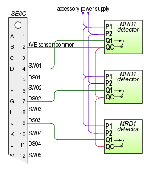
Fig. 1 - MRD1 to SE8C detector wiring
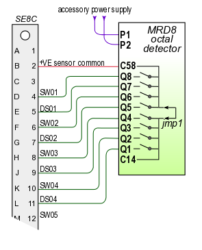
Fig. 2 - MRD8 to SE8C input wiring
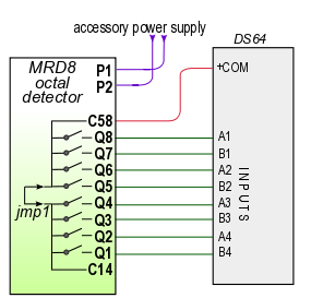
Fig. 3 - MRD8 to DS64 input wiring
|
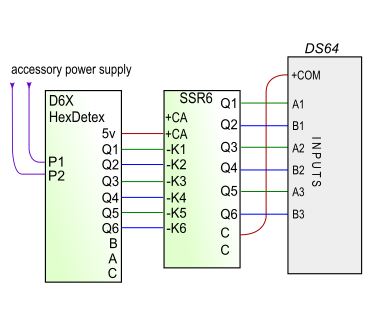
Fig. 4 - D6X HexDetex to Digitrax DS64 input wiring
|
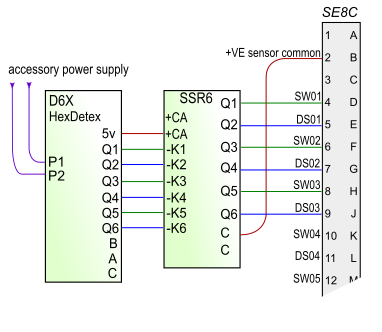
Fig. 5 - D6X HexDetex to Digitrax SE8C input wiring
|
DS74 and SE74:
Connecting an Azatrax detector to a Digitrax DS74 or SE74 is very similar to the DS64 and SE8C.
Examples are shown below in figures 6 and 7.
• When one MRD8 is connected to two decoder circuits, remove the jmp1 jumper block on the MRD8.
This will keep the reference voltages of the two decoders separate.
|
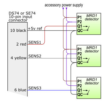
Fig. 6 - MRD1 to Digitrax DS74 or SE74 input wiring
|
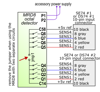
Fig. 7 - MRD8 to Digitrax DS74 or SE74 input wiring
|
Configuration of the Digitrax decoders and choice of control software is up to the user.
Azatrax does not provide software.
For instructions how to wire Azatrax infrared train detectors to Viessmann or Märklin s88 feedback decoders click here.
To see all Azatrax infrared train detectors click here.
Send questions or comments via our contact page.
© copyright 2009-2022 Azatrax LLC, Longmont, Colorado
|
|