|
|
|
|
|
How to configure a crossing signal system for your model railway
|
To help you choose the right number of train detectors and crossing signal controllers, find the configuration that best represents your grade crossing on your layout.
• Trains travel in one direction on each track
• Trains travel in both directions on each track
• Both directions with station stop or switching near the crossing
• When there is a turnout near the grade crossing
• One track with three block occupancy detectors
|
One-way rail traffic
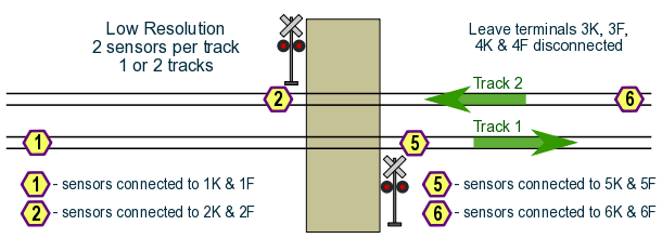
Trains travel in one direction only on each track, and normally do not make stops near the crossing.
This is called Low Resolution detection because only two train sensors are used on each track. The MRX3 controller is able to watch one or two tracks in low resolution mode.
How it works: When a train travels from left to right on Track 1, it is detected by sensor #1. The MRX3 will activate the crossing signals for up to 30 seconds. Once the train reaches sensor #5, the signals stay on until the train leaves sensor #5.
Similar operation occurs on Track 2 when a train moves from right to left.
|
The following module is required for this installation:
• One MRX3 controller with four sensors
|
One track, trains travel in both directions:
|
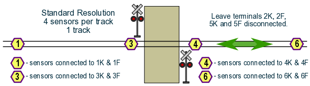
One track, two-way rail traffic
When Sensor 1 detects a train, the controller will activate the signals. The train has up to 30 seconds to reach Sensor #3. As long as the train is on either Sensor #3 or Sensor #4, the signals will flash. When the end of the train clears Sensor #3 and Sensor #4, the controller will turn off the signals.
Similar operation happens for trains moving from right to left.
|
The following module is required for this installation:
• One MRX3 controller with four sensors
|
This diagram shows sensor locations for the MRX3 control circuit.
If using an MRX2 controller, swap the locations of sensor #4 and sensor #6.
|
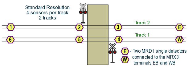
Two tracks, two-way rail traffic
For this double-track crossing, trains travel in either direction on each track.
As in the example above, 'standard resolution' is used (four sensors per track).
Sensor E and Sensor W are two single train detectors, which connect to the MRX3 controller.
|
The following modules are required for this installation:
• One MRX3 controller with six sensors, and
• Two MRD1-NV single detectors
|
|
One track, two-way traffic, with stops near the crossing
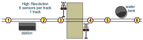
Trains travel in both directions. Trains might stop at the station or water tank.
If trains might stop or change direction within the crossing detection zone, one or two additional sensors help to maintain prototypical crossing signal operation. We call this 'high resolution' because the extra sensors give the controller a more accurate picture of where the trains are and which direction they're moving.
The controller will activate the signals when Sensor #1 detects a train approaching from the left. If the train stops at the station before it reaches Sensor #2, then the signals will turn off after 30 seconds, even if part of the train is still on Sensor #1.
When the train begins moving to the left again, the signals will re-activate when the train reaches Sensor #2. The train has another 30 seconds to reach Sensor #3 to keep the signals activated.
The signals remain active as long as the train is on Sensor #3 or Sensor #4. Once the train clears both Sensor #3 and Sensor #4 the signals will turn off.
|
Similar operation happens for trains moving right to left, which may or may not stop at the water tank.
The following module is required for this installation:
• One MRX3 controller with six sensors
|
Multi-track crossings
For crossings with multiple tracks, beyond the two-track examples shown above, use one MRX3 controller for the first one or two tracks, then add one or more MRD6X HexDetex™ expander units for the remaining tracks.
The MRD6X HexDetex™ expander is available with four or six infrared train sensors. Sensor configuration is similar to the MRX3 controller.
|
|
When there is a turnout near the grade crossing
Often there is a turnout (track switch, or 'points') near the grade crossing.
For correct operation, the crossing signals should respond to trains that are on the tracks aligned with the switch points. The signal system should ignore trains that are on tracks that are not aligned with the switch points.
The MRX3 controller can be easily configured for situations like this.
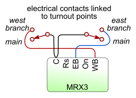
Turnouts must have an electrical contact linked to the points. This contact moves when the point rails move, and indicates the path that trains will travel.
Some manual switch throws are available with built-in electrical contacts. Some powered switch machines such as Tortoise and Cobalt also have built-in electrical contacts.
If your switch machine does not have built-in electrical contacts, adding a latching relay may be a solution.
|
|
Note that only sensors #1, #2, #5 and #6 are used.
|
|
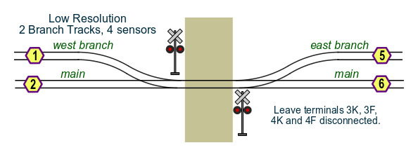
 Grade crossing between two branching tracks
This operates in 'low resolution' mode because two sensors are used for each possible path that a train can take through
the crossing.
Each turnout needs an electrical contact linked to the point rails. The contact should 'close' (make contact) when the
points are lined to the branch track, and 'open' when the points are lined with the main track.
Left-hand or right-hand turnouts may be used.
|
The following modules are required for this installation:
• One MRX3 controller with four sensors.
Each track turnout must have an electrical switch contact linked to the turnout points.
If your points machine does not have an electrical contact, check the latching relays page for a possible solution.
|
Note that sensor #6 is not used.
|
|
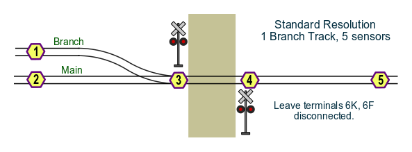
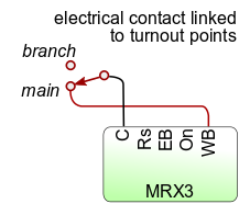 Single track grade crossing, one adjacent switch
This operates in 'standard resolution' mode because four sensors are used for each possible path that a train can take
through the crossing.
The turnout must have an electrical contact linked to the point rails. The contact should 'close' (make contact) when the
points are lined to the main track, and 'open' when the points are lined with the branch track.
The sensor that is not on the selected path will be ignored by the MRX3.
|
The following modules are required for this installation:
• One MRX3 controller with five sensors.
The track turnout must have an electrical switch contact linked to the turnout points.
If your points machine does not have an electrical contact, check the latching relays page for a possible solution.
|
This diagram shows sensor locations for the MRX3 control circuit.
|
|
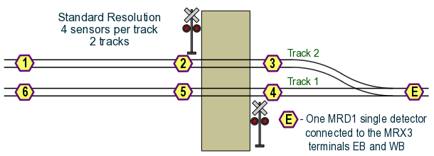
 Two tracks, two-way rail traffic with switch
For this double-track crossing, trains travel in either direction on each track. There is a switch near the crossing
where the two tracks merge.
As in the example above, 'standard resolution' is used (four sensors per track).
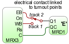
Sensor E is a single train detector, such as an Azatrax MRD1-NV detector.
|
The following modules are required for this installation:
• One MRX3 controller with six sensors, and
• One MRD1-NV single detector
The track turnout also needs to have an electrical contact linked to the turnout points.
If your switch machine does not have an electrical contact, check the latching relays page for a possible solution.
|
This diagram shows sensor locations for the MRX3 control circuit.
If using an MRX2 controller, swap the locations of sensor #4 and sensor #6.
|
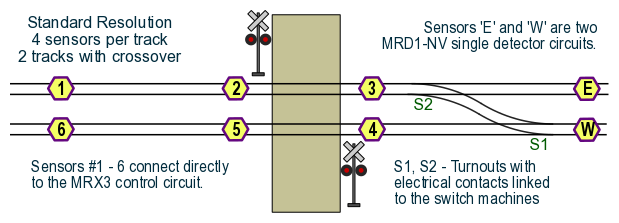
Two tracks, two-way rail traffic with crossover
'Standard resolution' is used (four sensors per track).
Sensors E and W are single train detectors, such as two Azatrax MRD1-NV detectors.
Detector wiring:
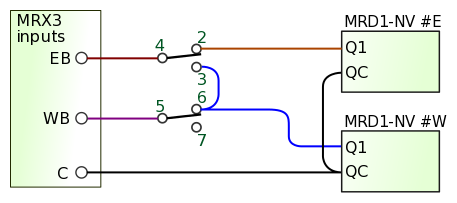
Switch machine contacts are shown with switches in the 'Normal' straight-through position.
Terminal numbers shown here are for Tortoise switch machines.
Depending on switch machine orientation, connections at
2 & 3
may have to be swapped, as well
as 6 & 7.
|
The following modules are required for this installation:
• One MRX3 controller with six sensors, and
• Two MRD1-NV single detector
One track turnout needs to have an electrical contact linked to the turnout points.
If your switch machine does not have an electrical contact, check the latching relays page for
a possible solution.
|
[Back to the top]
© copyright 2009-2025 Azatrax LLC, Longmont, Colorado
|
|