|
|
|
|
|
Automated Model Railroad Exhibit
|
Automatic controller alternately runs two model trains in opposite directions around a single-track demonstration layout
 A simple effective way to demonstrate railroad freight transportation at public exhibits and museum displays.
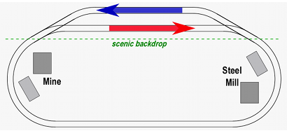
This is a single-track oval with a passing siding hidden behind the scenic backdrop. The blue train consists of hopper cars loaded with coal or ore. It travels counter-clockwise around the track, appearing to take its load from the mine to the steel mill.
After one trip around the loop, the blue train stops on its siding. The red train, consisting of similar but empty hopper cars, then makes a clockwise circuit around the loop. It is taking the empty hoppers back to the mine. When the red train disapperas behind the backdrop and returns to its siding, it stops, the blue train starts again, and the cycle repeats.
The theme can be developed further by adding a similar track to the right of the first one:
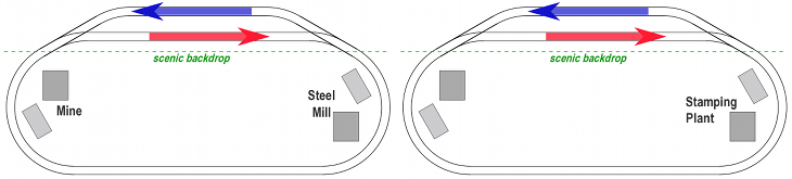
On the oval to the right, the blue train takes gondolas loaded with steel coils to the stamping plant, while the red train returns similar empty gondolas back to the steel mill. If space permits, a third loop can be added where trains take finished goods from the stamping plant to a distribution center or shipyard.
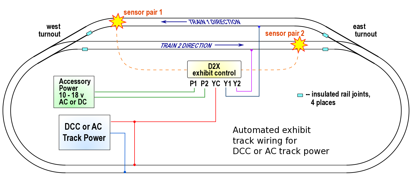
 How it works: The D2X exhibit control circuit has two infrared train detectors. The sensors for one detector are placed at the end of one of the passing sidings, and the sensors for the second detector are placed at the opposite end of the other passing siding.
The D2X has circuits to operate the switch machines and to turn the power on & off to the two track sidings.
An accessory power supply is required.
Choose a power supply suitable for your switch machines.
• 'Snap' (solenoid type) switch machines usually work best on 12 to 18 volts AC or DC.
• Slow motion motors need 10 to 15 volts AC or DC. The motors run on DC, the D2X circuit will convert an incoming AC voltage to DC.
The accessory power supply must have enough power to actuate two switch machines at the same time.
The Azatrax PS1235 12v dc power supply will work with slow motion switch machines and most snap switch machines.
Do not use with a capacitive discharge (CDU) power supply.
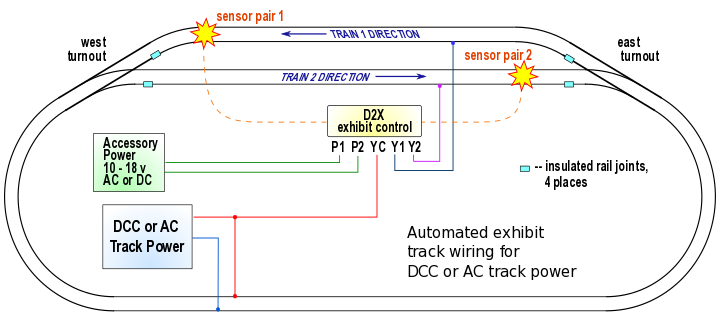
Exhibit layout for trains operating on DCC (digital) or AC track power.
AC powered locomotives (such as American Flyer) must have their reversing units locked so they always run forward.
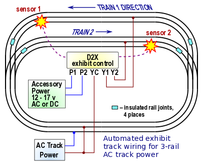
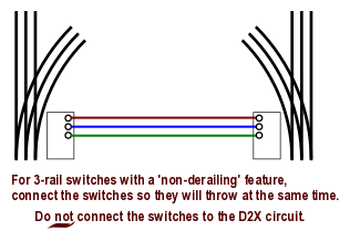
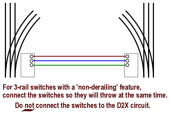
Exhibit layout for 3-rail track.
AC powered locomotives must have their reversing units ("E-units") locked so they always run forward.
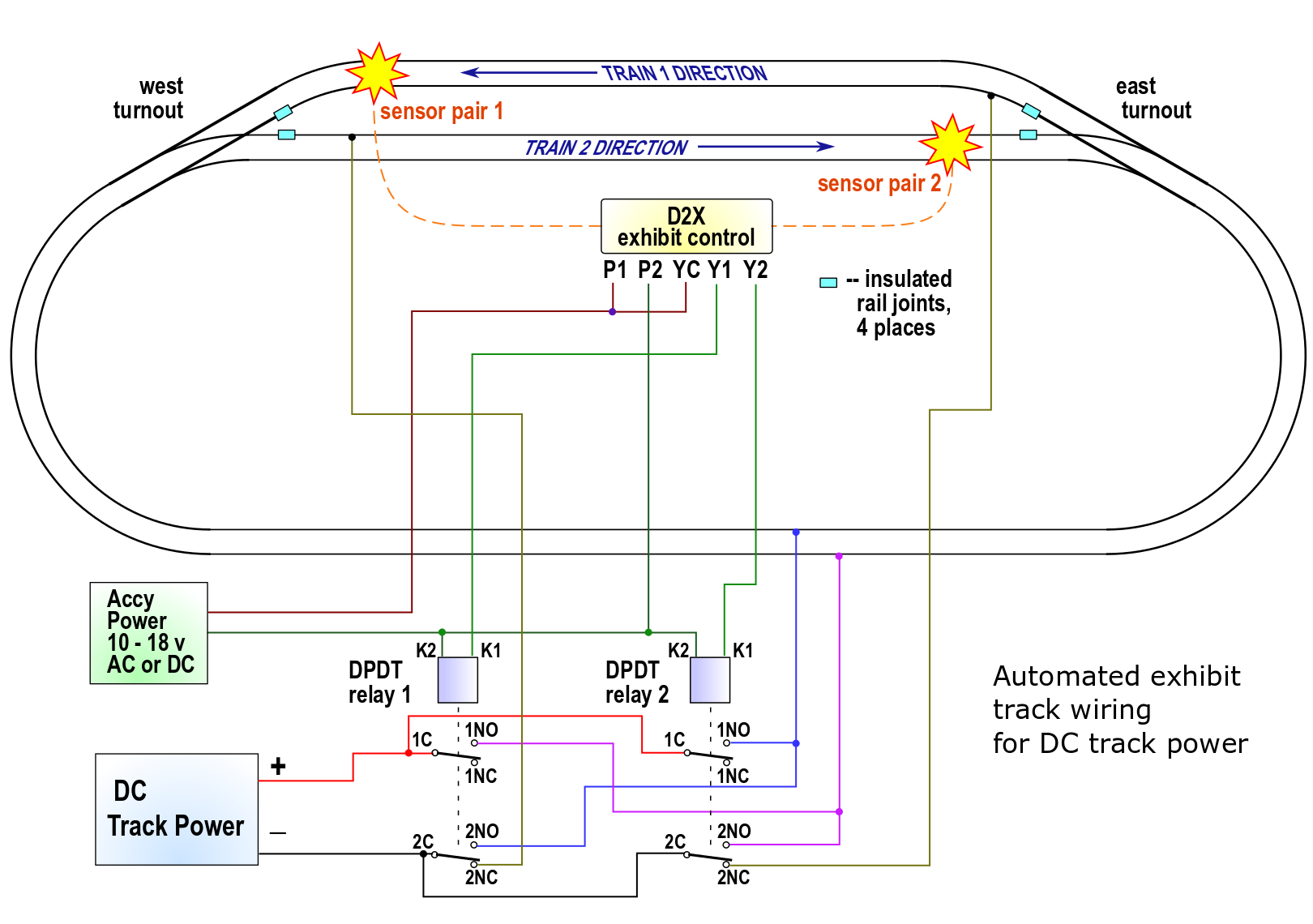
Layout with 2-rail DC track power
Traditional analog DC model trains change direction by swapping the +/- polarity of the track power. To accomplish this on the exhibit layout requires two DPDT relays as shown on the following diagram.
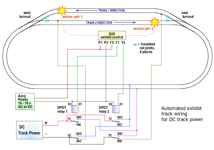
Exhibit layout for trains operating on analog DC track power.
When the train 1 has entered its siding and trips its detector, the controller turns off Relay1, waits a few seconds, then turns on Relay2. This stops train 1 and starts train 2. When train 2 returns to its siding and trips its detector, the controller turns off Relay2, waits a few seconds, then turns on Relay1. This stops train 2 and starts train 1 again.
The relays control power to the sidings and also control the +/- polarity of the track power.
|
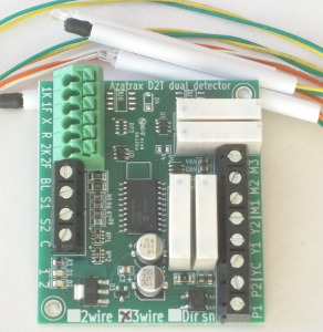
Each D2X exhibit control circuit includes two IR sensor sets.
Choose the D2X exhibit control circuit that is right for your switch machines.
|
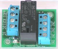
Analog DC-powered layouts also require two DPDT relays.
MRAPR-12v DPDT relay
coil voltage 10 - 17v AC or DC
contacts rated for up to 8 amps
|
|
For analog DC powered layouts, consider using a PFRR controller.
The PFRR features an adjustable acceleration/deceleration rate.
The D2X controllers on this page start and stop the trains abruptly.
© copyright 2009-2021 Azatrax LLC, Longmont, Colorado
|
|