|
|
|
|
|
Model Railroad Turn-around Track Wiring
How to wire a cross-over reversing track on your two-rail oval layout for automatic operation
|
|
Adding a cross-over track to a basic oval railroad layout permits a train to reverse its direction around the loop, allowing more interesting operating possibilities. The reversing feature requires a bit of extra wiring on layouts with two-rail track, but it is not difficult.
[Click here to review reverse loop fundamentals]
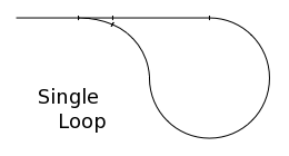
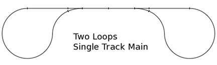
Here is one way to automate the track power polarity switching as well as the track switches on this type of track plan. The operator manually sets a track switch to select the route the train will take, and the automatic system takes care of the rest.
The solution shown here works equally well for DC, AC and DCC layouts.
This system, shown above, divides the track power into two districts - a 'Loop' district and a 'Main' district. In this example, the Loop district is the cross-over track, and the Main district is the oval track. Track power is routed from the power pack, or 'throttle,' through the MREV polarity controller, then to the two track power districts. The MREV Polarity Controller independently manages the polarity of the two track power districts.
In the diagram above, we've colored one rail red, the other black. The red rails are connected to the 'South' power leads - 'MS' on the Main district and 'LS' on the Loop district. The black rails are connected to the 'North' power leads, 'LN' and 'MN.'
There are two junctions where a train can cross from one district to the other. An MRD2 dual train detector is at each junction. It controls the track switch, or turnout, to prevent derailments, and also alerts the MREV polarity controller when a train is about to exit the cross-over track and enter the main line.
At junction 'M' the red rails meet each other and the black rails meet each other. At junction ''X' the like-colored rails are across from each other.
Wire the west switch machine to MRD2 #1 so the points align with junction 'M' when detector '1W' is triggered. Wire the east switch machine to MRD2 #2 so the points align with junction 'X' when detector '2E' is triggered. Either slow motion switch machines or coil-operated 'snap' switch machines may be used.
Note that the distance between detectors '1W' and '2E' must be longer than the longest train that will use the cross-over track.
Each junction also has an MRD1 single detector. Detectors '3' and '4' alert the MREV polarity controller when a train is about to enter the reversing section.
The MRD2 and MREV circuits have non-volatile memory. They remember the switch positions and polarity settings when layout power is turned off.
Components for the single reverse loop control system may be ordered separately or as a package. Detector circuits and the MREV polarity controller require a power supply of 8 to 14 volts AC or DC.
[Click here for multiple cab control wiring info]
Questions? Contact us and we will help tailor a system that best fits your layout.
|
MREV Polarity Controller
|
$32.50
|
|
MRD2 Dual train detector
Includes two infrared sensor pairs (IrLEDs & photo-transistors)
|
$36.50
|
|
MRD1 Single train detector
Includes one infrared sensor pair (IrLED & photo-transistor)
|
$16.95
|
|
Tortoise slow motion switch machine
Circuitron part no. 800-6000
Includes DPDT contacts for frog power or signal routing
With this system, solenoid-type switch machines may be used instead.
|
$15.90
|
|
Accessory power supply, PS1206
Regulated 12vdc, 600mA, slim plug-in
One supply can power a dozen Azatrax circuit modules
|
$9.50
|
|
Package for Automated Single Crossover Track Plan
Everything needed for the oval-with-crossover system shown above:
MREV polarity controller
Two MRD2 dual detectors with IR sensors
Two MRD1 single detectors with IR sensors
Two Tortoise switch machines
Two PS1206 12vdc regulated power supplies
|
$175.00
|
|
© copyright 2009-2012 Azatrax, Longmont, Colorado
|
|