|
|
|
|
|
What is a latching relay?
|
A latching relay is a two-position electrically-actuated switch. It is controlled by two momentary-acting switches or sensors, one that 'sets' the relay, and the other 'resets' the relay. The latching relay maintains its position after the actuating switch has been released, so it performs a basic memory function.
The latching relay is similar to a two-position ('double throw') toggle switch. The handle of a toggle switch is physically pushed to one position, and it stays in that position until pushed to the opposite position. A latching relay is electrically 'set' to one position, and it remains 'latched' in that position until it is electrically 'reset' to the opposite position.
|
There are two kinds of latching relays:
|
| An electrically latched relay is a standard relay with one of its own contacts wired into its coil circuit. An external switch initially turns the relay on, then it is kept on by its own contact. An external reset switch interrupts power to the relay, which turns it off.
|
A bistable, or mechanically latched relay typically has two internal coils and an internal latch mechanism. Energizing one coil 'sets' the contacts in one position, and the contacts stay in that position until the 'reset' coil is energized.
|
|
The differences are:
|
Electrically latched relay -
• Uses a standard single-coil relay,
• Always resets when power is turned off,
• One contact is dedicated for latching control,
• 'Set' switch is a normally-open contact,
• 'Reset' switch is a normally-closed contact.
|
Mechanically latched relay -
• Uses a dual-coil or polarized single-coil mechanism,
• Maintains its position when power is turned off, so the circuit will be in the same state when power is turned on again,
• All contacts are available for other circuit functions,
• 'Set' and 'Reset' switches are both normally-open contacts.
|
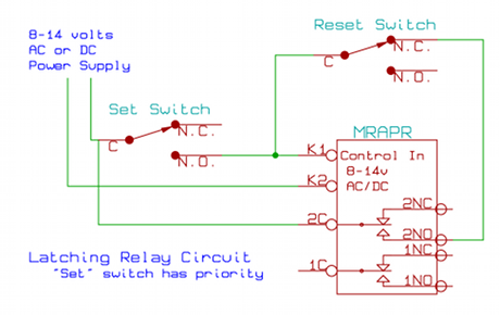
The two schematic wiring diagrams below show how to wire an electrically latching relay circuit. This creates a basic memory function... the relay 'remembers' which switch was pressed last.
For mechanical latching relays, click here.
In these circuits, the 'Set' switch is any normally-open switch or relay contact, such as an MRD1 train detector. The 'Reset' switch is any normally-closed switch or relay contact. When the 'Set' switch is pressed, the relay turns on. The relay stays on even after the 'Set' switch has been released because the relay coil (connections K1 and K2) now receives power through its own contact (connections 2C and 2NO).
When the 'Reset' switch is pressed, power to the relay coil is interrupted, causing the relay to turn off. This breaks the connection through contact 2C-2NO, so the relay stays off.
This type of memory circuit is called 'volatile' memory because when the power supply is turned off, the relay returns to its off state. When the power supply is turned back on, the relay will stay in its off state until the 'Set' switch is pressed.
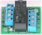
The relay used here is any standard relay with two or more sets of contacts, or 'poles' (DPDT, 3PDT, 4PDT, etc.) such as the MRAPR auxiliary power relay. The MRAPR relay includes diodes across the coil to protect the switch contacts from 'flyback' voltage, and it can be used in both AC and DC circuits.
See the note about switch contact ratings.
This first schematic is a circuit where the 'Set' switch has priority. This means that if both the 'Set' and 'Reset' switches are pressed at the same time, the relay will turn on.
The next schematic shows a circuit where the 'Reset' switch has priority. If the 'Set' and 'Reset' switches are pressed simultaneously, the relay will turn off.

For mechanical latching relays, click here.
© copyright 2009-2020 Azatrax LLC, Longmont, Colorado
|
|