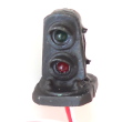
 Ground level signals, also known as ground signals or dwarf signals, are often used to indicate the position of track switch points.
These are 2-color signals that show green when the track switch is lined for the main track, and red (sometimes yellow) when the switch is lined for the siding or branch track.
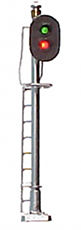 In places where a ground level signal is not easily seen, the signal may be placed on a mast or pole.
Model railroads with 'snap' type switch machines such as Atlas, Bachmann or Kato need to use a
latching relay to operate a ground signal.
For turnouts that use slow motion switch machines such as Tortoise motors,
Cobalt Classic, SwitchMaster or SwitchTender, the Azatrax GS-CA and GS-CC adapters make it easy to
install a 2-LED signal to show the position of your track switch.
The GS-CA and GS-CC do not work with a Ciruitron Smail™ switch machine. On a regular Tortoise switch machine,
connector pins 1 & 8 are directly connected to the motor, so the voltage at 1 & 8 is DC,
and it changes +/- polarity only when the motor changes direction. The GS-CA uses "+" polarity to
light one of the signal LEDs, and "-" polarity to light the other LED.
With a Smail, pins 1 & 8 are connected to a DCC bus. DCC is an alternating voltage, it is constantly changing
polarity from "+" to "-" and back again. The GS-CA is therefor lighting one LED
then the other in rapid succession, so it looks like both are constantly illuminated.
There are no access points to the actual motor voltage inside the Smail, so there is no place to connect the GS-CA.
The above also applies to "digital" versions of Cobalt™ switch motors.
GS-CA and GS-CC adapters also do not work with servo type switch machines such as the Walthers switch controls.
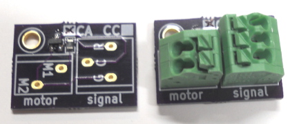
Available with solder terminals (left) or spring terminal blocks (right).
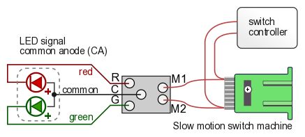
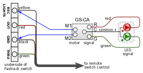
The GS-CA and GS-CC circuit boards have two terminals that connect to the motor of the slow motion switch machine.
Three other terminals connect directly to the signal - green, red and a common return wire. The circuit board has a built-in resistor to limit the LED current. No other resistors are needed.
The GS-CA circuit is for LED signals with common anode (common positive) wiring.
This includes most signals with two separate green and red LEDs.
Nearly all signals made by Custom Signal Systems, NJ International and Details West are common anode.
The GS-CC circuit is for LED signals with common cathode (common negative) wiring.