|
|
|
|
|
Use infrared train detectors to avoid collisions at model railroad track crossings
|
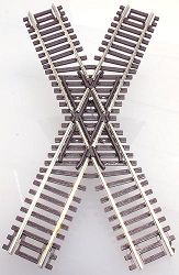
A level track crossing, often called a diamond crossing, creates visual interest on your model railway. It enables you to fit more track in limited space. It also affords operating challenges.
The obvious risk at a diamond track crossing is that of train collisions. Train operators must be familiar with the layout and must remain vigilant not only of their own train's location and direction, but also of possible conflicting traffic on the intersecting track.
An automated collision prevention system at your diamond crossing reduces the anxiety when novice or guest engineers are operating on your layout.
A simple system using just two relays can be used with 3-rail track.
Click here for the diagram [pdf].
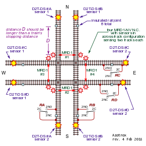
The diagram below shows how to add automatic crash protection by using two Azatrax D2T-DS infrared train detectors.
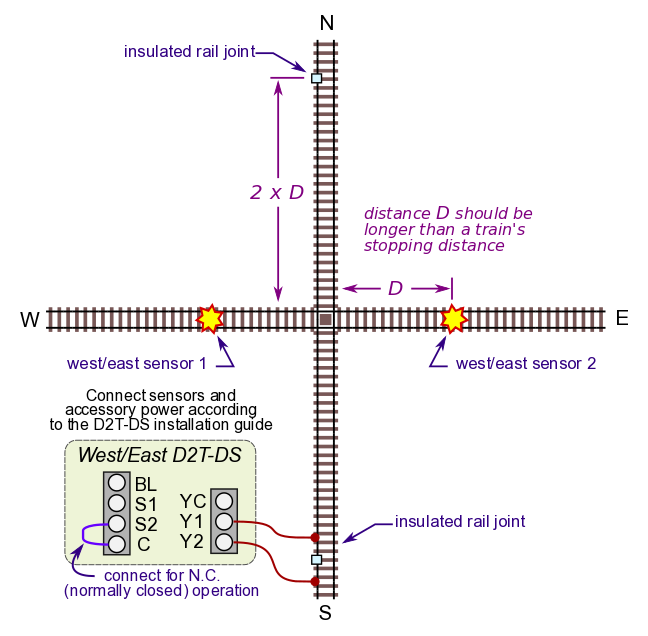
Step 1, protect the West-East track
The Azatrax D2T-DS is a dual infrared train detector. It uses its own infrared light, so it can be used in bright or dark environments. The two sensors (each comprised of an IR LED and receiver) may be placed in the roadbed flush with the ties, or can be placed on either side of the tracks. See the D2T-DS installation guide for more information.
Create an isolated section of track on the North-South track by placing two insulated rail joints (or gaps), one on each side of the crossing. The distance from the crossing should be longer than twice the stopping distance of a train. The reason for this will be seen
in Step 2 below.
The infrared sensors are placed on the West-East track. The distance from each sensor to the crossing should be more than the stopping distance of a train.
Install the D2T-DS dual detector and connect its sensors and accessory power according to
the D2T-DS installation guide.
Configure the D2T-DS for normally closed (N.C.) operation
by connecting terminal S2 to C with a short wire.
Connect D2T-DS terminals Y1 and Y2 to the track as shown.
How it works: When an east-west train detectors trips the first IR sensor, the D2T-DS will open its connection between terminals Y1 and Y2. This interrupts power to the isolated rail section of the North-South track, preventing a north- or south-bound train from reaching the crossing. After the end of the train clears the second IR sensor the D2T-DS re-connects power to the North-South track.
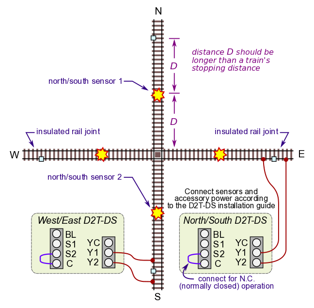
Step 2, protect the North-South track
Now make a similar installation of a second D2T-DS to protect the North-South track. Insert two insulated rail joints on the West-East track. As above, the distance from each insulated joint to the crossing should be more than twice the stopping distance of a train.
Install the two IR sensors on the North/South track. The distance from each sensor to the crossing should be at least as far as the stopping distance of a train.
Install the D2T-DS dual detector and connect its sensors and accessory power according to
the D2T-DS installation guide.
Configure the D2T-DS for normally closed (N.C.) operation
by connecting terminal S2 to C with a short wire.
Connect D2T-DS terminals Y1 and Y2 to the track as shown. Now your crossing is completely protected.
Why is distance 'D' important? For two reasons:
- Suppose a train is on the West-East track and the locomotive is near the crossing. A second train approaches on the North-South track. The second train enters its isolated track zone and coasts to a stop because power has been cut off by the West/East D2T-DS.
The North/South train must stop before it triggers an IR sensor. If does trigger an IR sensor, it will cause power to be cut off to the West-East track. Both trains will then stop, and there will be gridlock on your layout.
- Gridlock situation - Suppose two trains approach the crossing at almost the same time. Both the West-East and North-South isolated sections will be 'live' because there are no trains on the crossing. So both trains continue to approach.
One train will reach its IR sensor first, cutting off power to the other track. If the second train stops before it reaches its IR sensor then the first train will continue through the crossing and after it clears, the second train will start again.
But if the second train does trigger its IR sensor, the first train will also stop and your layout will be gridlocked. The simplest way to clear this is with a manual push button.
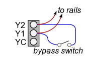 Manual bypass switch:
Connect a normally open (N.O.) momentary switch from D2T-DS terminal
'Y1' to 'Y2.'
As long as 'Y1' is connected to 'Y2' power will be supplied to the isolated track, regardless of whether a train is on IR sensors or not.
Manual bypass switch:
Connect a normally open (N.O.) momentary switch from D2T-DS terminal
'Y1' to 'Y2.'
As long as 'Y1' is connected to 'Y2' power will be supplied to the isolated track, regardless of whether a train is on IR sensors or not.
Connect a release button to one or both D2T-DS circuits.
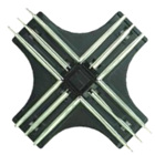
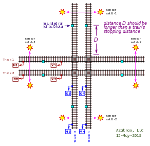 Quad diamond crossing:
Where a dual-track rail line crosses another dual-track rail line at grade with optional signals.
• Click on the drawing to download the full pdf document.
For completely automated operation, no gridlock and startup-safe:
Download these documents for systems that will not gridlock and will always start up safely after power has been interrupted.
These systems are suitable for unattended displays.
|
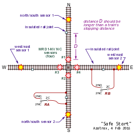
Single diamond, one single track crosses another single track.
• Click on the drawing:
|
Quad diamond, a double-track line crosses another double-track line.
• Click on the drawing:
|
For questions or comments, please use our contact page.
D2T-DS direction sensing train detector
Activates two different circuits depending on train direction. Sometimes you only want to activate a circuit or accessory if the train is moving in one direction, but not when it is moving in the other direction.
You can set up a D2T-DS for one of the following modes:
- Normally open, momentary - for actuating 'snap' switch machines or solenoid-operated semaphores that require brief momentary power only.
- Normally open, sustained - turns on a signal or other circuit when the train is between the two IR sensors.
- Normally closed, sustained - turns off a circuit when the train is between the two sensors. Can be used to protect trains at a level diamond crossing (interlocking).
|
Include infrared sensors?
|
© copyright 2009-2021 Azatrax LLC, Longmont, Colorado
|
|